It depends on the equipment. With certain system voltages (4160, 12.5-13.8 kV) there is sort of a default voltage class of 5 kV or 15 kV. 400-575 V is generally 600 V class, etc. But the "odd" voltages (230/240, 2400, 7200) don't really have a "home" or there is a voltage class but it's an oddball such as 2.5 kV class or 8 kV class which sometimes you find out there. That's with for lack of a better word, "standard" switchgear, MCC, etc.
But it doesn't end there. Some 600 V gear spacing is ridiculously close. Like I struggle to assemble it with lugs and maintain even a 3/8" spacing so some glastic, some taping, and a lot of swearing comes into play. Siemens and Aucom are two names that come immediately to mind but ABB has their day too. Typically everyone else has a a minimum 3/4" and more like 1" spacing everywhere for 600 V class, which meets the 25 mm "standard" bus gap. Now if I run the calculations this ultra-close equipment will end up with lower arc flash because there is a smaller bus gap to radiate heat from so using 25 mm is "conservative". The 25 mm rule generally holds true for 600 V class until you get into transformers where bus gaps just about go out the window.
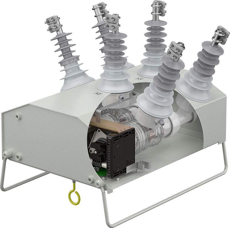
The opposite is true in the medium voltage world where you might see ultra-close bus gaps such as on the terminals of the Joslyn Clark disconnect switches that are adopted by many manufacturers but frequently it goes much wider. This is where I have something of a problem with it. There is no "standard" like the underlying UL creepage distance minimums built into UL 489 and 1066 for instance so there is no uniformity among manufacturers. 5 kV equipment though generally uses a 4" (104 mm) bus gap but 2.5 kV class equipment uses more like 2.5" (64 mm), and a lot of 5 kV class equipment is more like 4.5-5". When you build it the general rule is to make it as wide as possible but usually you are restricted by the terminals. And some of it is built closer together and just uses phase barriers to push the distances a little. This is particularly true of vacuum interrupters where the contact gaps internally are under 3/8" and externally you need just enough clearance for the vacuum bottle, so all kinds of fiberglass and other solid insulation is used to push the bus gaps as tightly as possible. For example one of the popular OEM vacuum interrupters that comes almost "plug and play" is from Tavrida. It is one of the smallest units out there. They make basically one size...38 kV rated. Then depending on the insulators and bus arrangements attached to get air gap everything has to stretch out and you get the "porcupine" look. See the picture below to see what I mean. The OEM breaker module on the left is sitting down on it's "back" horizontally underneath the insulators inside the box on the right which would be what would be mounted outdoors on a pole.
https://arjaynet.com/images/arjay/templ ... roduct.jpgSee the following image for the underlying detail:
https://www.tavrida.com/images/example/i-70.pngSo not to be coy here and obviously this isn't quite the comparison I want to make but I couldn't easily find similar images for 5 or 15 kV class equipment. But the point is...what bus gap do we use here?
Frankly, I've kind of given up and just use the default table values. It works decently on the gear that is relatively mass produced where all manufacturers tend to look identical to each other but that's as far as it goes. As you look closely and just when you think it's "all the same" and there is remarkable similarity on a lot of it, not the least of which because of the fact that there are few actual manufacturers and a whole lot of trading going on where no manufacturer actually makes everything in house. Not even the huge names like AB, ABB, or Siemens actually truly make everything. For instance AB for years has sold contactors that are considered by many to be the gold plated standard for NEMA style contactors all the while selling them with Cutler Hammer Form C MCP's in their starters along with just about everyone else. Now they are using ABB MCP's. And when it comes to IEC contactors it seems like virtually everyone is either using the LSIS one or the Sprecher-Schuh one just with their particular brand name on the contactor. CT's and VT's generally come from a scant small number of sources and it's one of the few things (ITI) that GE...err ABB actually makes themselves even if they bought up someone else. So it's not really surprising that the bus gaps are all very similar among "brands" when there are only a tiny number of actual manufacturers.
In the past I've only had to take notes of a few key values for each piece of equipment and the only physical measuring necessary, and this is a bit of a stretch, was for cable and bus size. But now unless we accept defaults there is a lot more data to use such as actual enclosure size so if I'm already out there with a plastic tape measure, it doesn't hurt to go ahead and record bus gap values too. Frankly I'm not even sure where to go on this. If we use actual bus gap values, it quickly "blows up" the arc flash equations. I can sort of accept the underlying theory and I'd expect the results to be basically linear because if we accept that the arc resistance is basically very similar and that generally we get the same arc voltage for a wide variety of fault currents, then ignoring the effects of the arc at the cathode and anode we would expect something basically linearly related to bus gap. But the empirical formula tends to "blow up" on bus gaps especially when you start plugging in more realistic values. Then again it "blows up" at least in the 2002 model even with extremely long working distances so I'm not sure whether or not any of this is actually realistic or adds much value. I mean the underyling data at least in the 2002 model rarely went above 1-2" for testing and bus gaps are a big deal more in the medium voltage world where they are all well over 2" so this is where validity of the model might be questionable. Unlike the 2002 version where you could actually see the underlying test data, I haven't come up with an excuse to purchase and it sounds like wouldn't have access to the thousands of test cases in the 2018 model to actually verify any of this.


